Time:2022-07-15 Views:994
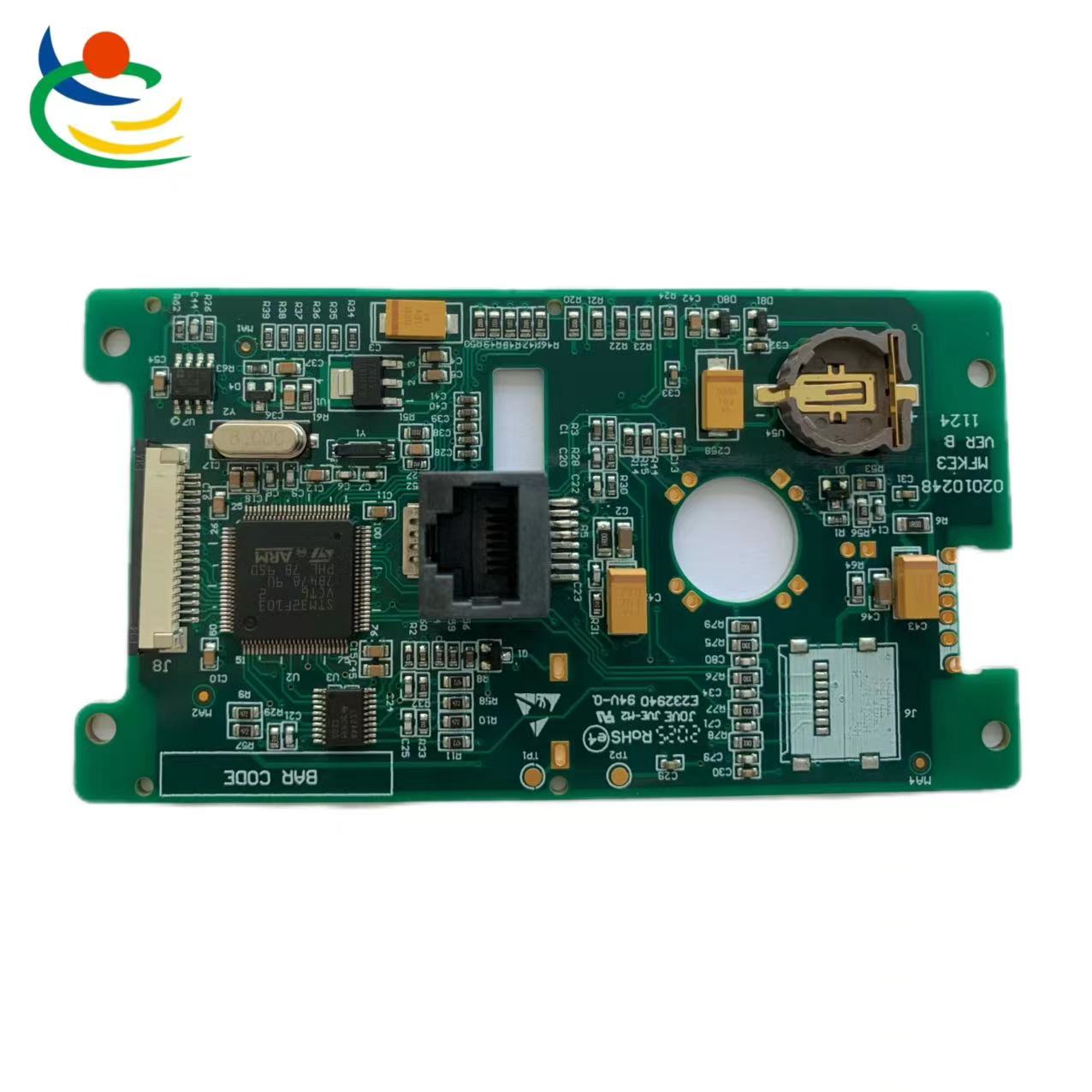
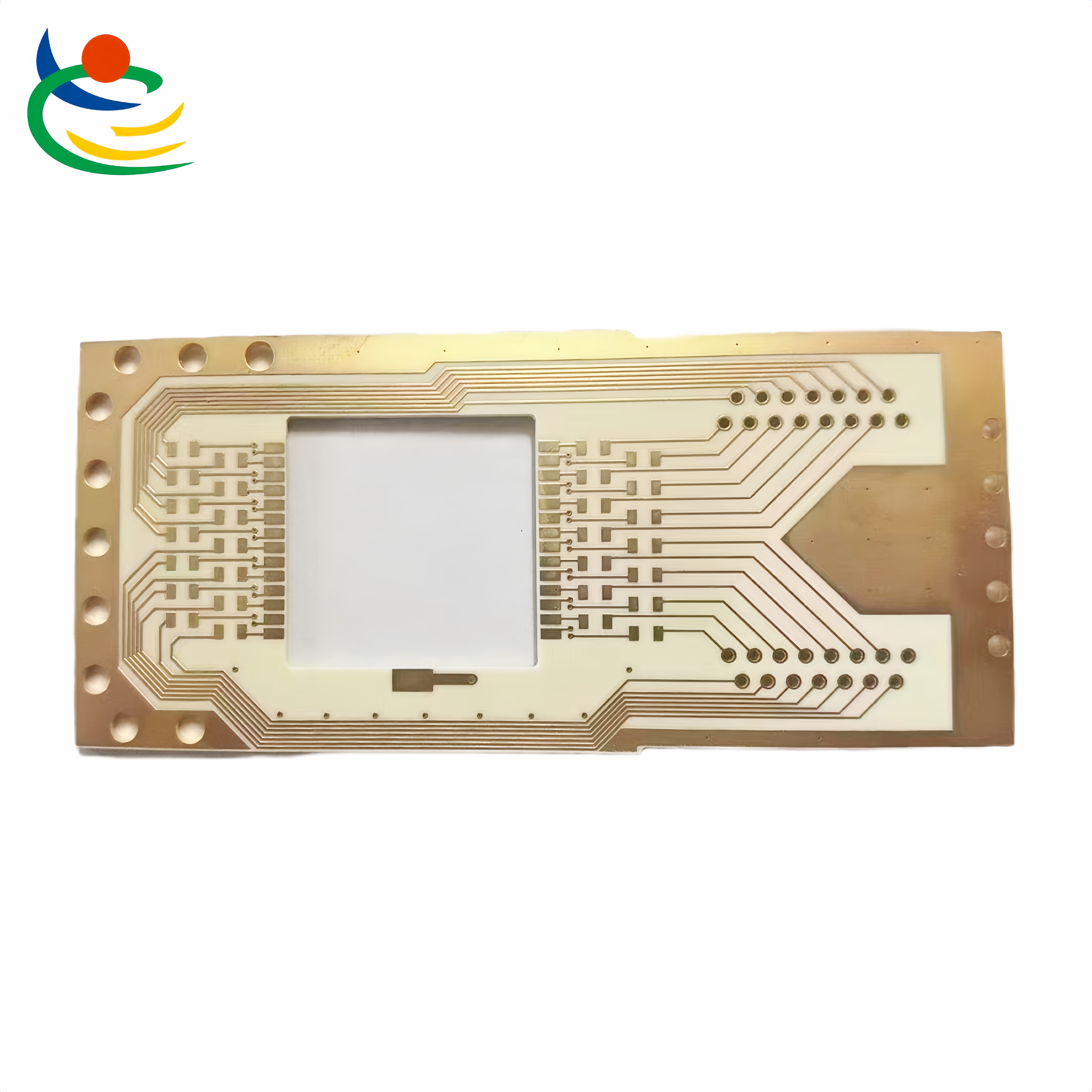
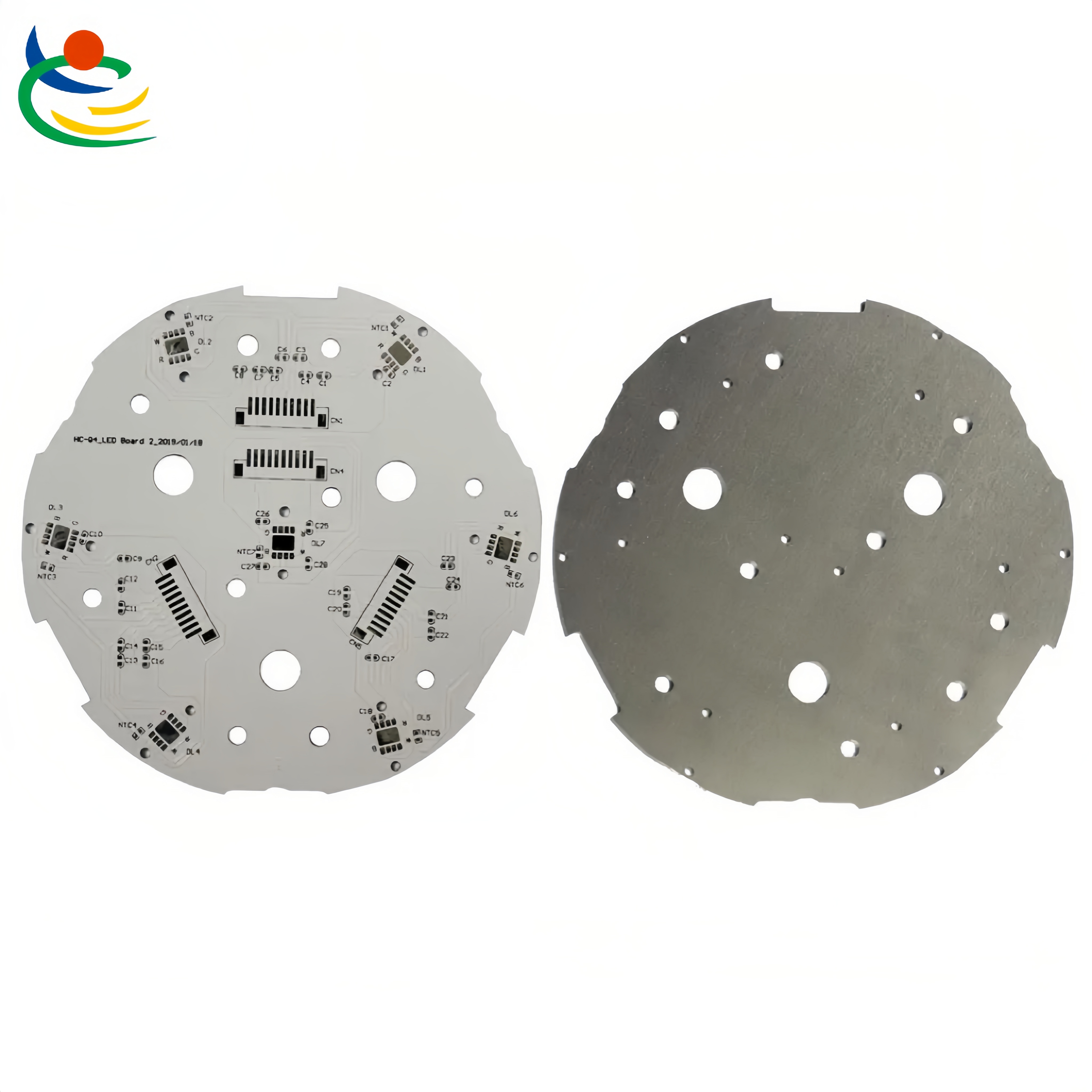
FPC flexible circuit board, English name Flexible Printed Circuit, commonly known as "soft board", also known as flexible circuit board, is made of flexible insulating substrates such as polyimide or polyester film, which is highly reliable. A stunning flexible printed circuit board. It has the unique characteristics of high wiring density, light weight, thin thickness and good bendability. Flexible printed circuit boards are also divided into single-sided, double-sided and multi-layer boards.
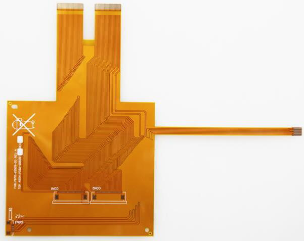
Flexible circuit boards are mainly used in the joint deployment of electronic products. Its advantage is that all lines are equipped and arranged. It saves the co-signer of parallel cables; it can increase the degree of softness. Enhance the assembly of three-dimensional space in a limited space; it can effectively reduce the output and the size of the product. Increases the convenience of carrying; also reduces the weight of the final product.
The scope of this standard covers flexible circuit single-sided, double-sided and multi-layer boards. The flexible circuit board mentioned in this standard refers to the single, double and multi-layer flexible copper foil substrate with polyimide (PI) or polyester (PET) as the base material, which includes adhesive (Adhesive, 3L-FCCL) and adhesive-free (Adhesive, 2L-FCCL) flexible copper foil substrates.
The purpose of this standard is to establish a general rule for the identification of the appearance quality of the relevant flexible circuit boards. As a basis for the identification of the appearance quality of the flexible circuit board products between Tianpai enterprises and suppliers, it is necessary to help improve the production technology and reduce the damage. Resource consumption and background pollution caused by abandonment.
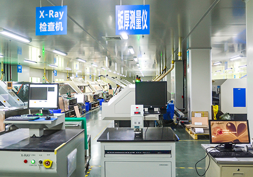
The test methods explained in this specification use visual inspection, magnifying glass, ruler and gauge as the main inspection and inspection methods and tools. When indispensable, other suitable test spectrographs or facilities must be used for inspection and inspection.
1. Appearance of the substrate film surface:
The allowable defect range of the appearance of the substrate film surface where the conductor does not exist is listed in the table. It is not allowed to have other bumps, creases, wrinkles and attached foreign bodies that affect the use.
2. Appearance of the cover layer:
Defects in the appearance of the cover film and cover coat: Permissible range, bumps, creases, wrinkles and delaminations that affect the application are not allowed.
3. Deviations between the concatenated disk and the cover layer:
The deviation e of the joint disk and the cover layer is less than ±0.3mm when the external dimension is less than 100mm, and the allowable deviation is less than ±0.3% of the external dimension when the external dimension is more than 100mm.
4. Infiltration of adhesive and covering coating:
The infiltration degree f of the adhesive and the covering coating should be less than 0.2mm. However, at the joint plate, plus the deviation of the cover layer and the deviation of punching, the minimum ring width g≥0.05mm must be satisfied.
5. Discoloration:
The conductor under the cover layer is discolored. After 96 hours of humidity resistance at a temperature of 40°C, a humidity level of 90%, and a humidity resistance test of 96 hours, it must still meet the requirements of voltage resistance, buckling resistance, bending resistance, and welding resistance.
6. Leakage of coating layer:
For the missing coating of the coating layer, try according to the requirements of solderability. Tin should not be stuck on the conductor of the missing coating layer.
7. The electroplating joint is not good:
The coating is not allowed to have delamination, the width W1, the length L, the conductor width W after processing, and the poor bonding of the coating cannot damage the reliability of the contact area.


+86 18825066881 (Mr. Liu)

sales@lhdxlb.com

For inquiries about our products or price list, please leave us and we will contact you within 24 hours.